
Railway Crossing Signal
We will discuss the design of a railway crossing signal. The control rules are well known, but as there may be some variants, let us lay down the details. The railway consists of two tracks. Each is monitored by three sensors L (left), M (middle), and R (right).

We assume that a train may come from either direction on each track, but only one train (per track) can enter the sensor zone (we call the space between sensors L and R the sensor zone). We assume also that trains may be short or very long, i.e. a train in the sensor zone may cover no sensor, one sensor, two sensors, or all three sensors at the same time.
The control system should cover all imaginable situations, switching the crossing lights according to the following rules:
- Both lights are switched off if the control system is not working.
- The yellow lights are flashing if there is no train between sensors
LandRor a train has just passed the sensorMand is still between sensorsMandL(R), moving towardsR(L), i.e. leaving the sensor zone. - The red lights are on if there is a train between sensors
L(R) andM, moving towardsM, i.e. approaching the road. - Both red and yellow lights are on if the situation is not definitely defined: after a system start, when an unexpected sensor signal is received, and when the expected sensor signal has not come after a certain time (train disappeared?). These situations are considered unsafe ones and can be resolved only by manual control: if the situation is cleared, the operator may reset the system.
Design
Section titled “Design”There is seldom “the best” solution for a control system. The solution depends on decisions taken by a system project leader (which state machines to use) as well as on details of the specification of the state machines themselves. Eventually, the specifics of the implementation tools may also influence the solution. When specifying the state machines, a designer may minimize the number of states by using input actions intensively (Mealy model). Or he may not bother about the number of states, trying to achieve a clear, understandable state machine (Moore model).
The example demonstrates how to cover unusual situations in a control system. Of course, a state machine that covers only a correct sequence of sensor changes is very simple to design and does not present any challenge to other solutions. For a simple system, when only the “sunny day” scenario is considered, any solution will do. Problems arise from the rarely occurring but dangerous, erroneous situations which make the design of control systems difficult and justify all the effort needed to design a good control system.
The control system will be designed as a modular system which can be expanded for any number of tracks, each having three sensors: L, M, R.
”Obvious” solution
Section titled “”Obvious” solution”Let us consider first only the problem that seems to be the basic one: how to identify the train position that determines the crossing lights.
If you think a while about it, you may find very soon an obvious solution: the system has to “know” that a train entered the sensor zone, i.e. it has passed the sensor L or R and moves towards the sensor M. This information seems to be sufficient to switch on the red light. When the train is over the sensor M, the red light stays switched on. When eventually the train leaves the sensor M, the red light can be switched off. The information: moving towards (plus staying over the sensor M) and left sensor M seems to be sufficient to control both lights: red and the flashing yellow one. Thus, it seems that, using a hardware analogy, one flip-flop should be enough to control the lamp or, in other words, two states will do.
This solution has one major limitation: it uses the signal edges for control: in hardware it would mean - the rising edge of the L sensor sets the flip-flop, the falling edge of the M sensor resets it. This kind of control is not always possible and it is considered unreliable. Anyway, for our exercise, as we want first to show a simple solution, we are generous and accept for a while this “edge”-based solution and assume that we are able to “detect” the direction of signal changes.
Before showing the error in the solution, we will underline once more the difference between the “sunny day scenario” and the real world. The simple analysis above has been limited to the case in which only the correct, i.e. the most probable, sequence of events is considered (the sensor changes according to the train’s movement). By restricting our analysis in this way, we lose sight of the actual control problem. In the discussed example, there are at least the following situations that need to be considered, namely the system behavior
- on startup,
- when the “train gets lost” (it entered the sensor zone but never left it),
- when an unexpected sensor signal occurs, for instance, a sensor
Msignals the presence of a train though there has been no train yet detected in the sensor zone.
If we take into account all that we have said up to now, we could specify the state machine shown below. The diagram shows the basic two states: NoTrain and Present to realize the basic control.
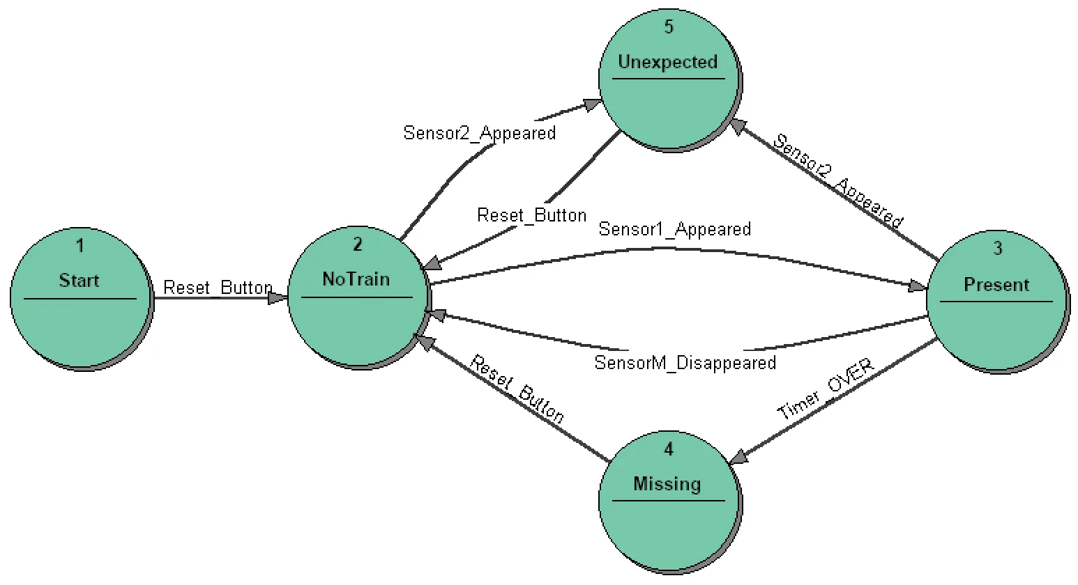
In addition, to make the control system more realistic, we introduced:
- a state
Startwhich allows the state machine to switch on the crossing lights after the start-up, - states
MissingandUnexpectedto handle the two above-mentioned erroneous situations.
If we try to define transition conditions and actions for the Unexpected state, we encounter some difficulties. Let us consider the following situation: a short train has entered the sensor zone, the state machine has detected the change of the L sensor and has changed its state from NoTrain to Present, where it has switched on the red light and has stopped the yellow flashing light. The train continues its movement towards the sensor M. Eventually, the train leaves the sensor L, but it has not arrived at sensor M yet. At this moment, the sensor L signals a (new?) train. What should the state machine do now? Our first reaction — change to the state Unexpected — will not work. This has been the condition to make the transition from NoTrain to Present. So, if we use the same condition for the transition from state Present to Unexpected, this transition will be performed immediately when entering the state Present. We see that the state machine cannot express the different situations in the analyzed control system with two states. To specify the behavior of the light control, we need more states.
The ultimate Control
Section titled “The ultimate Control”After the first unsuccessful trials, we jump over the many intermediate solutions that could have been explored and present the complete solution.
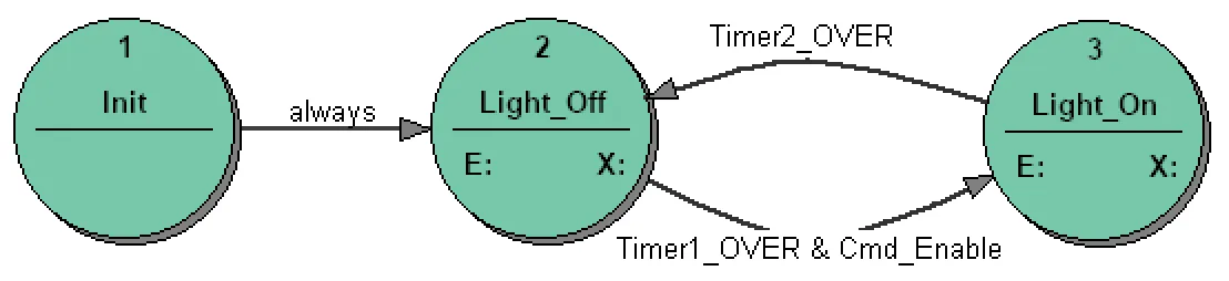
The control system consists of three state machines: CrossingSignal, TrainPosition, and Flash. TrainPosition is the state machine which realizes the control sequence for one direction. Flash is a state machine which generates the yellow flashing light. CrossingSignal is the main state machine which controls directly the red light. CrossingSignal enables/disables the functioning of Flash by commands Cmd_Enable (1) and Cmd_Disable (2).
State Machines
Section titled “State Machines”TrainPosition
Section titled “TrainPosition”The TrainPosition state machine “follows” the train and at any time presents the train position by its states. You need two TrainPosition state machines for one rail: one state machine for each direction. The state transition diagram for TrainPosition is as follows:
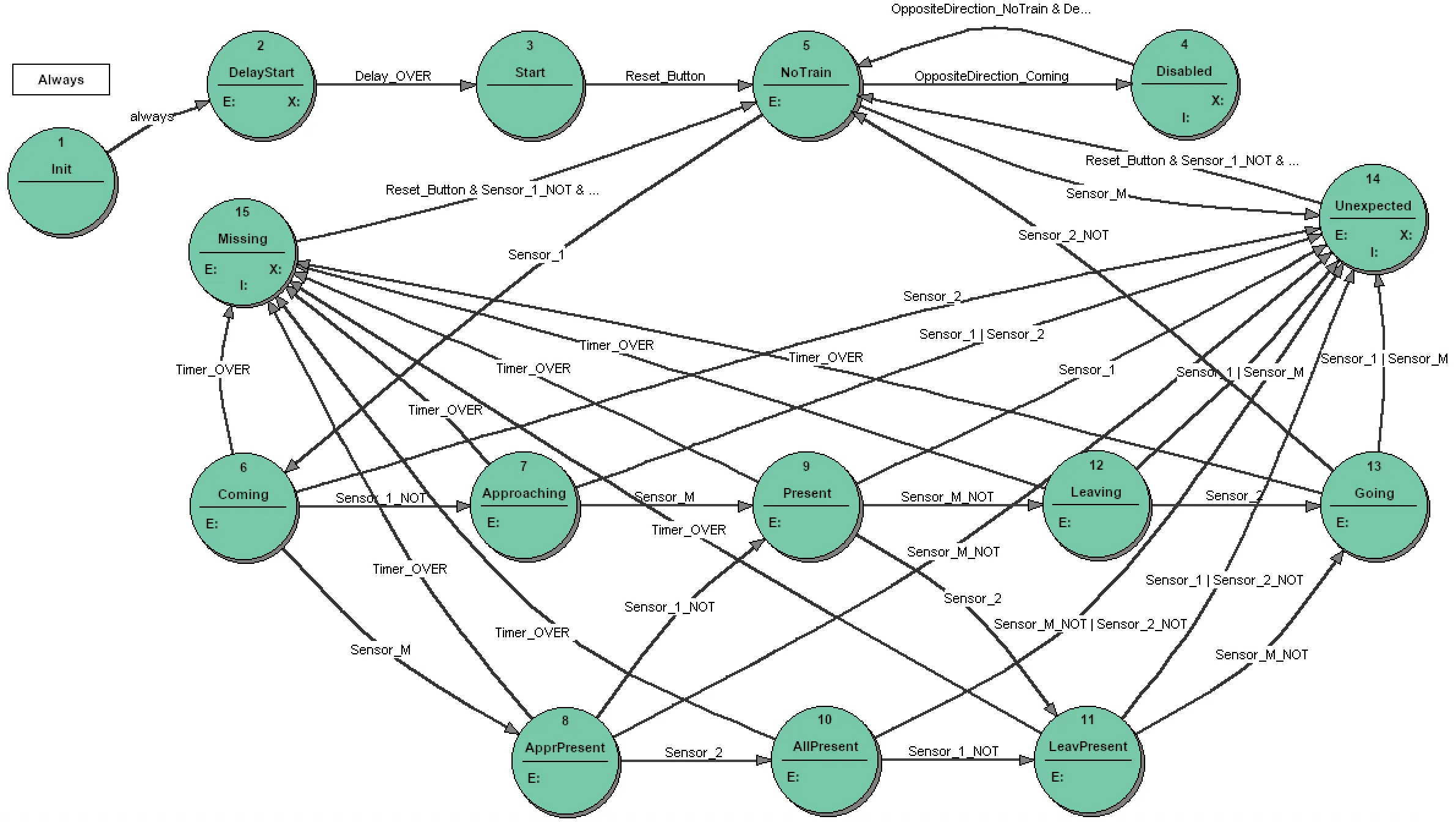
The state transition diagram displays only the states and transition conditions. The complete specification requires the entry, exit, and input actions which are only indicated in the diagram by the letters E:, X:, I:. The full specification is included in state transition tables.
If there is no train between sensors L and R, the state machine stays in the state NoTrain. Depending on the train length, many state sequences are imaginable, for instance:
- for a short train which covers only one sensor at a time:
NoTrain -> Coming -> Approaching -> Present -> Leaving -> Going -> NoTrain
- for a long train which covers two sensors at a time:
NoTrain -> Coming -> ApprPresent -> Present -> LeavPresent -> Going -> NoTrain
- for a very long train which covers all three sensors at a time:
NoTrain -> Coming -> ApprPresent -> AllPresent -> LeavPresent -> Going -> NoTrain
The functioning of the two TrainPosition state machines for a rail is mutually exclusive: if one state machine goes into the state Coming, the “partner” state machine goes into the state Disabled. This arrangement avoids erroneous signaling of failures: a proper sequence of events (sensors) for one direction would be a failure for the other direction.
CrossingSignal
Section titled “CrossingSignal”As the TrainPosition state machine represents the train position at any time, CrossingSignal can react directly to the states of the four TrainPosition state machines that belong to a track (two directions per rail, two rails). CrossingSignal is a state machine with the states Off, On, Undefined, and Going, reached from an initial Init state once the TrainPosition state machines have started. Off and Going switch the red light off and enable the yellow flashing light, On switches the red light on and disables the flashing light, and Undefined switches on both lights for the unsafe, not-clearly-defined situations. The state machine moves between these states directly on the individual TrainPosition states (Coming, Leaving, Going, NoTrain, Unexpected, Missing, …).
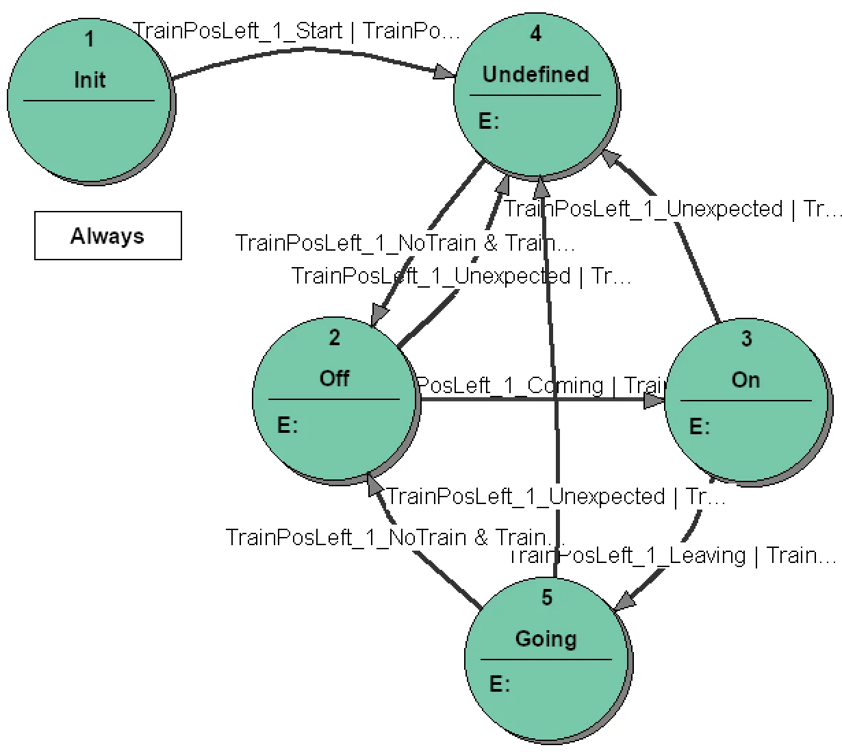
The yellow light is not controlled directly by the CrossingSignal state machine. There is a simple Flash state machine which generates the flash-cycle and controls the yellow light. The CrossingSignal state machine controls the behavior of the Flash state machine using commands: CmdEnable and CmdDisable.
System for 2-track railway
Section titled “System for 2-track railway”The following diagram shows the state machines system required for a 2-track railway. It is interesting to note the unconventional system structure. It is not a typical hierarchical system. The main state machine CrossingSignal, which in fact controls the lights, reacts directly to the states of the state machines TrainPosition, which it takes as inputs. The state machines TrainPosition create a layer which “translates” the train movements into definite train positions. Knowing the train positions, CrossingSignal only has to evaluate a small, explicit set of state conditions to control the lights. The approach can be extended to more tracks, and you may notice that, once a state machine has been designed, further instances can be added to the project very easily.

Conclusions
Section titled “Conclusions”The case study represents fragments of a typical design procedure. We start to analyze the control system, producing the first trial solution. Doing this, we learn better the requirements. After several trials, we understand the problem and we do the first system design where we decide about the overall structure of the system: inputs, outputs, type and number of state machines, and their interface (in fact, we decompose the control task into manageable entities and determine how these entities cooperate). The system design may not be the ultimate one. It may be changed if, during the state machine specifications, we encounter problems whose solutions require changes in the system design.
We could not show you all the steps, errors made, all the defeats and triumphs which accompany the design process. We just presented the first unsatisfactory trial and then the ultimate solution.
Is the solution the best one? Nobody can answer this question. We like it and it works, so we stopped searching for better solutions.
You may have questions, especially considering the TrainPosition state machine. It may seem an overkill to use so many states. Considering the basic representation of train movement, we started with two states (NoTrain and Present) and ended with nine states (NoTrain, Coming, … Going). We have shown that the minimal solution could not work, but we have not proved that we really need nine states. Maybe a smaller number will do. We have, of course, tried other solutions. If we were to design a hardware system with a limited number of flip-flops (nowadays, this does not seem to be a problem either), we would try to minimize the number of states. Using Automata Theory design methods, we can arrive at a state transition diagram with a minimal number of states (we have done this and we have obtained a state transition diagram with five states as a minimum solution). There are two problems with this approach: (1) How many people know and are able to effectively use the Automata Theory methods? (2) A solution with the minimal number of states is often less comprehensible than a system with intuitively defined states.
In a software implementation, the number of states does not significantly influence the needed memory, so other factors are important. In software implementations, we should choose clear, understandable solutions. This should not be understood as an encouragement to overuse states. In this specific control system, we have the impression that the states used represent the train position very well, which is the essential information. Paraphrasing a well-known rule, we would recommend: use as many states as you find necessary but no more.
With this example of crossing signal control, we would like to pass a message: do not underestimate the control problem. At first glance, this kind of control may appear as a trivial exercise. It may be simple if we limit our considerations to a “sunny day scenario” with one train going in one direction without any practical value. It is a non-trivial problem if we discuss it seriously, taking into account the real situations which may occur in such a system. The task of a control system is to react not only to expected, routine sequences but to manage unexpected situations which may appear once a year or even once in the system’s lifetime. Correct action in these rare situations may save human life or save costly damage to hardware equipment.
Check out the specification details automatically generated by StateWORKS or install the IDE to inspect and test the system. You will see that the system fulfils the railway crossing signal requirements perfectly.