
About State Machines
State machines in the (software) control world
A state machine
Section titled “A state machine”Automata Theory distinguishes between combinatorial and sequential circuits. If inputs determine outputs, we have a combinatorial circuit; otherwise, a sequential circuit. A state machine is a specific implementation of a sequential circuit. A state machine is known under several names: state machine, finite state machine, automata, push-down automata (push-down state machines), Turing machine, deterministic state machine, statechart (Harel automata). Some of them are just the same. For instance, it is difficult to explain a difference between a state machine and a finite state machine, as the word “finite” is not unambiguously defined. To justify the name finite state machine, shouldn’t we also have an infinite state machine? The word automaton (automata) is used as a synonym for a state machine. In lexical analysis, a specific state machine called a parser (also called recognizer or acceptor) has been used.
In this paper, a state machine is considered as a description of the system control behavior: what to do in all imaginable situations. The base of a state machine is a state as complete information about the history of input changes. States represent all possible situations in which a control system may ever be. A diagram in Figure 1 shows the dependencies involved in a state machine functioning: both the State transition conditions and the Action conditions are functions of Inputs and a State.

Figure 1: State machine definition
The true sense of changing states is to perform some actions (except for a parser, where only state changes count). The behavior of the control system is then described by a transition table and/or a state transition diagram. The state transition diagram is a graphical representation where we use two elements: circles for states and arcs for transitions. To get the full information, we use, for each state, a state transition table which contains: transitions and their transition conditions, as well as all possible actions. Actions are performed on inputs or state changes. Therefore, we distinguish:
- input actions performed if input changes
- entry actions on entering a state
- exit actions on leaving a state
- transition actions while the state changes.
Effectively, several actions are performed just at the same moment. When an input change forces the state machine to change a state, all actions can be performed in the sequence:
- input action as the input has been changed
- exit action as the state machine leaves the present state
- transition action as the state machine changes a state
- entry action as the state machine enters a new state.
In practice, not all actions are used. For instance, we speak about:
- Mealy model if only input actions are used
- Moore model if only entry actions are used.
Figure 2 shows a state transition diagram of a state machine that controls the pressure in a vacuum chamber, and Figure 3 shows a state transition table of the state Starting. In the example, three types of actions are used: input, entry, and exit. We do not go into the details (syntax) of the presentation, as it depends on the tool used (the presented diagram and table have been created using the StateWORKS development system).
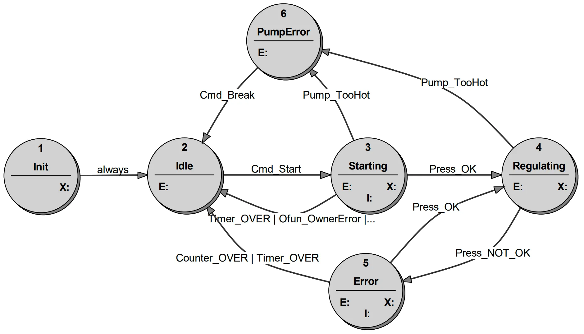
Figure 2: Example of a state transition diagram
Several activities are initiated. Waiting for pressure acknowledgements. Due to a Timer, a missing acknowledgement leads to a return to the Idle state. A too-hot pump leads to the PumpError state. Both erroneous situations generate corresponding alarms. An error when accessing the output function returns the state machine also to the state Idle: it does not make sense to supervise the pressure without having proper pressure limits (corresponding alarms are generated in the “Always” table).
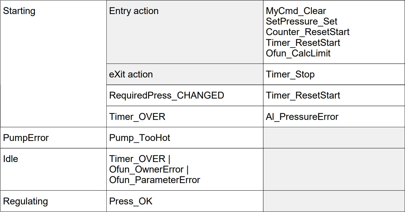
Figure 3: Example of a state transition table
State machine in hardware design
Section titled “State machine in hardware design”For completeness, we mention briefly the role of state machines in hardware design. As a rule, they use the Moore model (entry actions only), and the implementation uses a set of flip-flops (organized as a register), whose state is the state of the state machine. The use of state machines is rather obvious: the environment is a pure Boolean one, the tasks are relatively simple and limited to single state machines (if the application uses several state machines, they are not considered as a system of state machines but just single, separate state machines). The complexity of the control is these days located in the software.
State machine in software design
Section titled “State machine in software design”The real interest of the paper is the use of state machines in software design. The complexity of sequential tasks in software is huge. Any non-trivial software is a complex sequential system. The extreme examples are the operating systems of computers. Hence, one might think that state machines should have been used in software design. In practice, they are used with care and, as a rule, they are hidden in the code. There are countless possibilities to code a state machine using if-then-else and switch statements. The spaghetti code produced in that way can be simplified using a table-based solution. All of them are difficult to understand and error-prone. The basic source of errors is the state variable that can be manipulated everywhere in the code. In the case of many state machines, the requirement is often to consider them as a system of interconnected state machines. In the coded version, it is rather a dream.
Why do state machines fail?
Section titled “Why do state machines fail?”Theoretically, state machines could be used in the design and implementation of software control systems. Everybody knows them, as they are at least mentioned in some academic courses or training, but the idea that the entire software can be based on state machines is not understood and is considered an unrealistic undertaking. State machines are used in informal discussions or to solve some local control problems in a program. Several tools based on a state machine have been developed (SDL, UML, ASML, …), but they never found large acceptance. If applied, the tools are used in the initial specification phase of the project and then forgotten.
The specification is never perfect. During implementation, several changes are required, not only cosmetic but essential ones. They are never made in the specification but directly in the code. Over time, the gap between specification and implementation is growing. Eventually, we can only say “in code we trust”, as the initial specification has lost any credibility. Solving control problems directly in the code is the major reason for software malfunctioning. Understanding the software functioning by reading the code increases essentially the cost of software maintenance and changes.
There are several issues that are responsible for the situation. In the following sections, we will discuss some of them which we regard as essential obstacles to the broader application of state machines in software practice. First, we show that the implementation model of a state machine influences the specification.
Implementation model of a state machine
Section titled “Implementation model of a state machine”Thinking of a state machine, we must distinguish between a superficial representation of a control task and a definite specification of a state machine which is to be implemented. The following trivial example illustrates the problem: we want to switch a motor on and off using a toggle button (it has one stable position). Pushing the button switches the motor on (if it has been off) or off (if it has been on). We assume that the execution system is triggered to perform a transition by events: in that case, the events are changes of the input DI from LOW to HIGH and vice versa.
A first solution could be a state machine with 2 states:
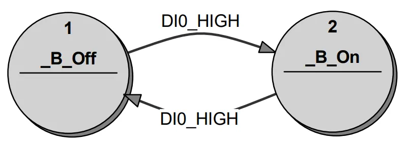
Figure 4: Two-state toggle
The motor will be switched on in the state _B_On and switched off in the state _B_Off. This implementation will work if the execution system performs only one transition at a time. Otherwise, it will oscillate between states _B_On and _B_Off until the input signal changes to LOW.
A second solution would be a state machine with 4 states, shown in Figure 5. In that case, the motor will be switched on in the state OnBusy and switched off in the state OffBusy. In addition, the states OnBusy and OffBusy “delay” the transition to the correspondingly stable states On and Off until the input signal goes to LOW. In this solution, the execution system allows several transitions at a time.
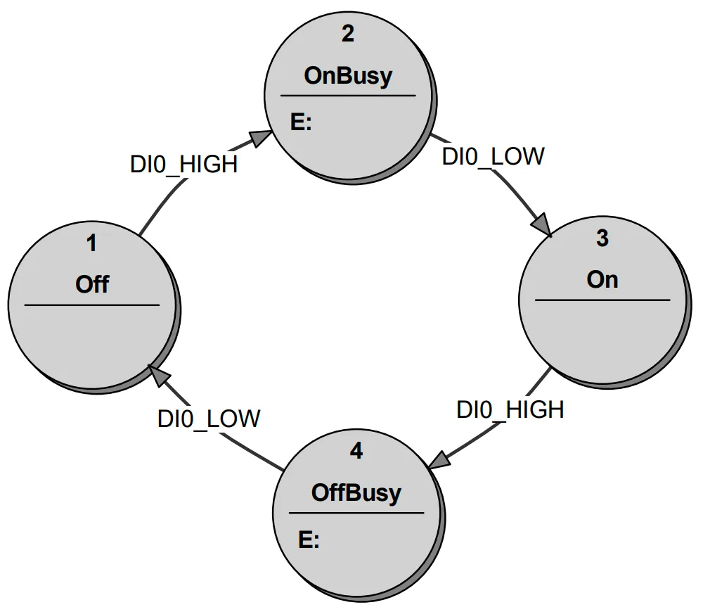
Figure 5: Four-state toggle
The example above shows that there are several specifications of control behavior. In other words, each of these specifications is correct, but the programmer has to program it differently.
A similar toggle problem exists if the trigger signal is a multivalued one. For instance, for a simple temperature regulation problem (air conditioning or heating), the input signal has 3 values: Temperature_HIGH, Temperature_OK, and Temperature_LOW. To specify the control problem for air conditioning, we use two signals, Temperature_HIGH and Temperature_LOW, as shown here:
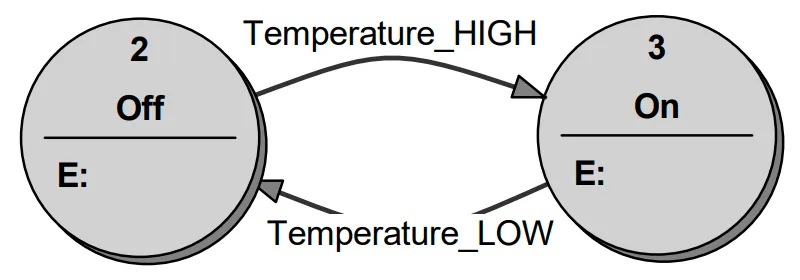
Figure 6: Temperature-based toggle
The implementation does not restrict the functioning of the execution system: one transition or several transitions at a time will do. If the air conditioning is off, the Temperature_HIGH signal changes the state to On (air conditioning will be switched on). If the air conditioning is on, the Temperature_LOW signal changes the state to Off (air conditioning will be switched off). The coded implementation is in that case extremely simple. Due to its sequence of changes: Temperature_HIGH - Temperature_OK - Temperature_LOW… The input signal performs the control directly.
Getting logical conditions (Positive Logical Algebra)
Section titled “Getting logical conditions (Positive Logical Algebra)”The major problem with implementing a state machine is the generation of logical conditions (State transition conditions and Action conditions). In the hardware environment, where state machines have found their original use, this problem does not exist: all signals are Boolean. In contrast, the state machines specified and implemented in software require logical conditions that are per se multivalued ones. Examples:
- Temperature can be at least
Low,OK,High - Commands may have several values:
Init,Start,Stop,Break,Continue - In a (hierarchical) system of state machines, the Slave state machines have many states that are used in transition conditions of a Master state machine.
In addition, many input signals can be unknown due, for instance, to a broken cable, which means that even digital input signals (considered as classical Boolean values) are in fact 3-value signals: Low, High, Unknown. The Temperature example needs probably also the value Unknown.
A Positive Logical Algebra solves this problem by creating a Virtual Environment which allows the specification of state machines for software using multivalued variables. The definition of the Positive Logic Algebra can be found in Appendix 1.
Hierarchical system of state machines
Section titled “Hierarchical system of state machines”If the control problem is complex enough, it becomes impossible to specify its behavior with a single state machine. Using several state machines could be a solution. Organizing such a system of state machines is a very difficult challenge. A coded solution would require a programmer to create a means of communication to exchange information among the state machines. This solution is very difficult to understand and test. It is also very difficult to present documentation of the control flow in the software. A hierarchical organization of state machines seems to be a solution.
Statechart implements this idea, assuming top-down design. It means that a designer starts with an initial bubble which represents the entire control. The initial bubble is then refined to express more details of the control. The weak point of the approach is the top-down design, which often cannot be used in control systems.
In contrast, using the bottom-up design, a designer starts with a specification of elementary units like motor control, gauge operation, pressure control, monitoring, emergency treatment, etc. The lowest level (Level 3) of state machines has direct contact with the physical world, reading hardware signals, measured values, and contacting external devices. The state machines on the lowest level are organized in functional groups, each group being controlled by a corresponding state machine. The state machines in Level 2 communicate with their slaves, accessing their states and sending commands. On the other hand, state machines in Level 2 may be controlled by state machines in Level 1, which read their states and send them commands. Eventually, at the top is a single Master state machine. Here an example:

Figure 7: Example of a hierarchical system of state machines
The decision about top-down or bottom-up design is, in practice, not that sharp. The analysis of the problem is often done as top-down, the design rather bottom-up. Often, while coding, the method changes; it is a trial-and-error process. Having a specification tool, it is easier to test different approaches; by a pure coding approach, eventually, the programmers have to settle for anything.
StateWORKS and the use of execution system
Section titled “StateWORKS and the use of execution system”Theoretically, it would be possible to code a StateWORKS hierarchical system of state machines, but the result will be as bad as with other coded solutions: the first approach will correspond to the specification, but introducing changes to the program will create a gap between the specification and implementation. The advantage of the StateWORKS solution is the use of a virtual environment which allows the creation of a runtime system that just executes the specification. Several projects have confirmed that this concept works.
The StateWORKS concept results in a strict separation of a data flow and a control flow in the software: the control flow is realized in a StateWORKS execution system and the data flow in (coded) output functions.
The human factor
Section titled “The human factor”A major factor in software development is the programmer. Without their acceptance, any concept will fail. In principle, programmers reject any idea which reduces the freedom of coding; they assume that they can code any problem regardless of its complexity. It is true, but the result depends on the programmers’ quality: top programmers deliver very good software; weak programmers create software catastrophes. Unfortunately, we do not have enough top programmers. We believe that the use of an executable state machine specification would make software development more effective, allowing the concentration of coding effort on programming the data flow.
We comment on two examples of software development where we have experienced the pitfalls of coding instead of state machine specification ourselves.
- Protocol specifications use state machine presentations. We had to use a Diameter failover protocol once. Studying the state machine presented in a corresponding telecommunication specification, we found a rather unusual notation there which makes the understanding quite difficult. First of all, we “translated” this diagram into a true state machine diagram and contacted the authors of the specification, suggesting replacing the state machine diagram in the specification. The contact showed that the authors had rather limited knowledge about state machines, and their conclusion was that “the programmers will do it”.
- Writing a User Interface is a standard occupation in many programs that communicate with a user. The controls shown on the screen may generate a message if activated, may be shown or hidden, enabled or disabled, etc. A typical approach is a chaotic scenario where the activation of buttons, text boxes, radio buttons, combo boxes, etc. is done in functions called during the execution of the program. In many cases, the state of the controls depends not only on the functions but on the actual situation (state of the application). Hence, we need additional variables which reflect the state of the application. But these variables depend also on the situation. In other words, a state machine whose states define unambiguously the situation would be a recommended solution. But how often is this understood and realized?
Conclusions
Section titled “Conclusions”The article has discussed the major problems that limit the true use of state machines in software:
- Incomplete understanding of an implementation model of a state machine
- Restriction of input variables to Boolean values
- Misunderstanding of a system of state machines
- Programmers’ resistance to a no-coding solution.
We have shown that the use of a Virtual Environment allows a full specification of the behavior beyond the true Boolean values. Such a specification can be carried out in an execution environment which eliminates the burden of coding the control flow. This solution works for a single state machine as well as a system of hierarchically organized state machines.
Appendix 1. The Virtual Environment using Positive Logic Algebra
Section titled “Appendix 1. The Virtual Environment using Positive Logic Algebra”Input Names and Virtual Input
Section titled “Input Names and Virtual Input”A state of an input is described by Input Names which create a set:
- input A: Anames =
- input B: Bnames =
- input C: Cnames =
- …
Virtual Input VI is a set of mutually exclusive (active) elements of input names. The VI always contains the element “always”:
VI =
VI =
VI =
Logical operations on Input Names
Section titled “Logical operations on Input Names”& (AND) operation is a set of input names:
| (OR) operation is a table of sets of input names:
~ (Complement) is a complement of a set of input names:
Logical expression
Section titled “Logical expression”A logical expression is an OR-table of AND-sets (corresponds to the disjunctive form of a Boolean expression):
Logical expressions are used to express any logical function.
Evaluation of a logical expression
Section titled “Evaluation of a logical expression”The logical value (true, false) of a logical expression is calculated by testing whether any of the AND-sets in the OR-table is a subset of VI.
Output Names and Virtual Output
Section titled “Output Names and Virtual Output”A state of an output is described by Output Names which create a set:
output Xnames =
output Ynames =
Virtual Output VO is a set of mutually exclusive elements of output names.
Virtual Environment
Section titled “Virtual Environment”The Virtual Name and Virtual Output, completed by State Names, create a Virtual Environment VE where the behavior is specified.